.avif)





Blogs
Stay updated with our latest blog posts.


Knowing exactly How We Test Flame Sensors During a Fall Furnace Tune-Up is the best way to prevent that frustrating moment when your thermostat clicks, the burners ignite with a reassuring whoosh, and the entire system suddenly shuts down just ten seconds later. This cycle of starting and stopping is a common reality for homeowners who skip their early fall pre-heating season maintenance. When your furnace locks out on the first truly cold night of the year, the culprit is rarely a catastrophic mechanical failure. Instead, it is often a lightly fouled safety component that has dropped below a critical electrical threshold.
Understanding this process reveals the difference between a superficial visual check and true mathematical verification. A proper diagnostic process does not rely on guesswork; it relies on exact electrical measurements to guarantee your heating system will perform when you need it most.
If you want to ensure your system is ready for the cold, exploring professional heating and cooling services is the smartest first step.
Modern furnaces are equipped with highly sensitive control boards designed to prioritize safety above all else. When a heating cycle begins, the inducer motor clears the exhaust flue, the igniter glows, and the gas valve opens. At this precise moment, the system must confirm that a fire has actually started. If the system fails to detect a flame within a few seconds, the control board immediately cuts the power to the gas valve. This rapid shutdown prevents unburned gas from pooling inside your heat exchanger and your home.
If this ignition sequence fails multiple times in a row, the furnace enters a state called a "hard lockout." The blower motor might run continuously to clear any residual gas, but the burners will refuse to ignite until the system is reset. In our years of providing heating service across Derby, KS, our team at MJB Heating & Cooling frequently encounters homeowners who assume the gas valve or igniter has failed. However, the most frequent offender we find is simply a dirty flame sensor failing to communicate with the control board.
To understand why a furnace shuts down so abruptly, you have to understand the specific job of the flame sensor. This component is remarkably simple in its construction: it is usually a thin, stainless steel rod encased in a porcelain insulator, positioned directly in the path of the burner assembly. Its primary job is to prove that a flame is present while the gas valve is open.
The sensor operates using a principle called "flame rectification." The furnace control board sends a continuous, alternating current (AC) to the metal rod. When the burners ignite, the flame itself acts as a conductive pathway. The fire essentially bathes the rod in ionized gases, which allows the electrical current to travel through the flame, ground out to the metal burner chassis, and convert into a tiny direct current (DC). The control board constantly monitors this returning DC current. If the current disappears, the board assumes the flame has blown out and immediately shuts the gas valve.
Just last autumn, our team responded to a Derby KS homeowner who experienced the direct result of a failed safety check during a sudden cold snap when their heater stopped working entirely. Our technician arrived within 10 minutes, quickly identifying that the system was short-cycling and locking out. After fixing the heater—and identifying a non-code pipe on the hot water tank in the process—the home was finally warm again. This kind of sudden, complete shutdown is exactly what the flame sensor is designed to trigger when it cannot verify combustion.
Because the flame sensor sits directly inside the fire, it is subjected to extreme temperature fluctuations. Over time, microscopic layers of carbon, dust from the indoor air, and natural oxidation build up on the surface of the metal rod. This buildup acts as an electrical insulator. Even a layer of oxidation so thin that it is barely visible to the naked eye can severely restrict the flow of electricity, causing the control board to lose the signal and shut the system down prematurely.
A common misconception in furnace maintenance is that a clean-looking component is a fully functional component. Many basic inspections involve a technician simply shining a flashlight into the burner compartment, noting that the flame sensor looks relatively shiny, and moving on. This approach leaves homeowners vulnerable to sudden breakdowns.
At MJB Heating & Cooling, our technicians differentiate themselves through technical precision. Rather than just "eyeballing" a sensor or wiping it down and hoping for the best, we measure the exact microamp (µA) draw to mathematically prove the component is working. This level of exactness is just as important as comparing reliable HVAC brands when installing a new system—you need concrete data, not assumptions.
The risk of relying on visual checks is that a sensor might conduct just enough electricity to keep the furnace running during a mild autumn afternoon, but fail entirely when the temperature drops sharply and the system is forced to run longer cycles. Relying on visual assumptions inevitably leads to unnecessary emergency service calls later in the season.
• Visual Inspection — What It Reveals: Checks for obvious physical damage or heavy, black soot buildup. — Reliability for Winter: Low. Cannot detect clear oxidation or micro-electrical resistance.
• Basic Wipe-Down — What It Reveals: Removes loose surface dust but leaves baked-on silica or carbon. — Reliability for Winter: Medium. May temporarily fix a short-cycling issue but lacks proof.
• Microamp (µA) Draw Test — What It Reveals: Measures the exact electrical current flowing through the flame. — Reliability for Winter: High. Mathematically proves the sensor will communicate with the board.
Testing a flame sensor requires specialized diagnostic tools and a strict adherence to safety protocols. Because this process involves interacting with live electrical currents and active gas combustion, it is strictly a professional procedure. We believe in full transparency about our diagnostic process. Just as one local customer noted during a spring maintenance visit when our technician clearly explained the testing performed before recharging their HVAC system, we apply that same educational approach to furnace safety checks.
Here is the step-by-step methodology our technicians use to verify your system's reliability:
1. Isolating the Power and Accessing the Control Board: The technician begins by shutting off the main power to the furnace to safely access the internal control board and the wiring harness leading to the burner assembly.
2. Setting Up the Multimeter in Series: Using a specialized HVAC multimeter set to read microamps, the technician disconnects the single wire leading to the flame sensor. They then connect one meter lead to the wire and the other lead directly to the sensor terminal. This places the meter "in series," meaning the electrical current must flow directly through the diagnostic tool to complete the circuit.
3. Initiating the Heating Cycle: Power is restored, and the thermostat is prompted to call for heat. The technician closely monitors the ignition sequence as the gas valve opens and the burners ignite.
4. Recording the Baseline Microamp (µA) Draw: Once the flame bathes the sensor, the multimeter captures the exact electrical current being generated by the flame rectification process. This baseline reading tells the technician exactly how degraded the sensor's electrical conductivity has become before any cleaning takes place.
By measuring the exact microamp (µA) draw, our technicians remove all the guesswork from the maintenance process. We know instantly whether the sensor is healthy, failing, or on the verge of causing a hard lockout.
To understand what our technicians are looking for on their multimeters, it helps to understand the scale of the electricity involved. A microamp is one-millionth of an ampere. Because the electrical pathway relies on the ionized gases of the flame itself, the resulting current is incredibly weak. However, modern furnace control boards are highly sensitive and require this tiny current to remain within a very specific numerical window.
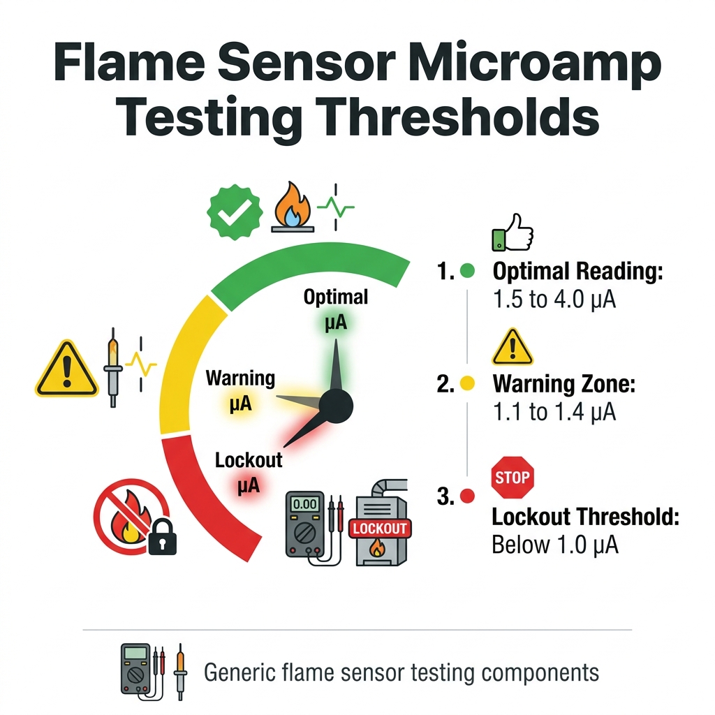
When the multimeter stabilizes during the heating cycle, the resulting number dictates our next steps. Here is how professionals interpret the microamp (µA) draw:
• 1.5 to 4.0 µA (Optimal Conductivity): This is the target range for a healthy, clean flame sensor. Readings over 1.5 µA indicate strong electrical conductivity, proving that the flame is easily completing the circuit back to the control board.
• 1.1 to 1.4 µA (The Warning Zone): Readings hovering in this range serve as an early warning sign of impending failure. The furnace will likely still operate, but the sensor is heavily insulated by oxidation. A sudden drop in gas pressure or a slight shift in the burner flame could easily push this number below the minimum threshold.
• Below 1.0 µA (The Danger Zone): Any reading below 1.0 µA is usually the threshold where the control board will trigger an immediate lockout. The board can no longer reliably distinguish between a weak flame and no flame at all, so it defaults to shutting down the gas valve for safety.
Knowing the exact number allows technicians to predict failures before they happen. If we record a baseline reading of 1.2 µA during an early fall pre-heating season tune-up, we know with certainty that the furnace will likely fail during the first major winter storm if left unaddressed.
Once a sub-optimal baseline reading is recorded, the technician moves to the restoration phase. The goal is to remove the microscopic layer of oxidation without damaging the stainless steel rod itself.
The professional cleaning process: Technicians use specific, non-abrasive materials—such as specialized cleaning pads or fine steel wool—to gently polish the rod. We never use standard sandpaper or emery cloth. Sandpaper contains silica, and if silica dust is left on the rod, the intense heat of the burner flame will melt it into a microscopic layer of glass. Glass is a perfect electrical insulator, which would permanently ruin the sensor's ability to conduct a microamp (µA) draw.
The critical final step: After the component is cleaned and reinstalled, the job is not finished. The most important part of the process is immediately re-testing the electrical draw. The technician hooks the multimeter back up in series and initiates another heating cycle.
We want to see the reading jump from the warning zone (e.g., 1.2 µA) right back up into the optimal range (e.g., 2.8 µA). Comparing the "before" and "after" numbers mathematically proves that the system's reliability has been restored. This mathematical verification is a cornerstone of our comprehensive fall furnace tune-up.
If the reading does not improve after a thorough cleaning, it indicates a deeper issue. The porcelain insulator on the sensor may be cracked and grounding out, or the control board itself may have a failing ground connection. Because we use a multimeter, we can immediately pivot to diagnosing these deeper issues rather than leaving you with a furnace that is doomed to fail.
September and October are the ideal months to identify and resolve these micro-electrical issues. Derby's rapidly dropping fall overnight temperatures create a unique challenge for heating systems. A furnace might run perfectly fine during a mild 60-degree afternoon, but those sharp temperature swings from day to night put immediate stress on untested safety components.
When the temperature plummets below freezing, your furnace has to run longer, more frequent cycles to maintain your indoor comfort. If a flame sensor is hovering in the warning zone, the sustained heat and prolonged operation during a hard freeze can easily push it below the 1.0 µA threshold, resulting in a sudden, highly inconvenient lockout in the middle of the night.
Catching a low microamp (µA) draw during the early fall pre-heating season provides immense peace of mind. You aren't just hoping your furnace will work; you know it has been mathematically verified to perform. We proudly serve Derby and surrounding areas, encouraging homeowners to schedule proactive maintenance to avoid the rush of emergency no-heat calls when the severe weather inevitably turns.
Understanding exactly how your furnace verifies its own safety is the first step in protecting your home from unexpected winter breakdowns. The difference between a true tune-up and a superficial check lies entirely in the data. By measuring the exact electrical draw of your flame sensor, professionals can guarantee that your system will communicate seamlessly with its control board all season long.
This precision prevents mid-winter lockouts and ensures your family stays warm when the Derby KS weather is at its worst. If your furnace hasn't been mathematically verified this season, now is the time to secure your comfort with a comprehensive, data-driven tune-up.
What should a flame sensor read in microamps?
A healthy, working flame sensor typically reads between 1.5 and 4.0 microamps (µA). When a professional tests the component with a multimeter, they are looking for a strong, steady current within this range. If the reading drops below 1.0 µA, the furnace control board will usually trigger a safety lockout.
Why does my furnace shut off after a few seconds?
This symptom, known as short cycling, is most often caused by the control board failing to detect a flame. Even if the burners ignite successfully, a dirty flame sensor cannot send the proper electrical signal back to the board. For your safety, the system immediately shuts the gas valve to prevent unburned gas from accumulating.
How do professionals test a flame sensor?
Professionals test the sensor by connecting a specialized HVAC multimeter in series with the sensor's wiring harness. While the furnace is actively firing, the meter reads the exact direct current (DC) being generated by the flame rectification process. This provides a mathematical baseline of the component's health.
What happens if a flame sensor goes bad?
If the sensor goes bad or becomes heavily insulated by oxidation, it loses its ability to conduct electricity. The furnace will attempt to start, the burners will ignite briefly, and then the system will shut down entirely. After several failed attempts, the furnace will enter a hard lockout and refuse to run until it is serviced.
Can a dirty flame sensor cause a mid-winter lockout?
Yes, a lightly fouled sensor is one of the most common causes of sudden mid-winter breakdowns. As the furnace runs longer and more frequent cycles during extreme cold, a sensor that was already struggling to conduct electricity can easily drop below the critical threshold, leaving you without heat on the coldest nights.


Our A/C stopped working on a Sunday and due to health issues, we needed to find a service company available on a Sunday. I called MJB and left a message on their emergency voice mail. Within 10 minutes Tom Buck called me to hear my description of the symptoms. He was just finishing an appointment in Wichita and would be on his way to my home on the south end of Derby. He arrived within 30 minutes! From start to finish he was the perfect example of what you could ever hope for in an HVAC tech and a human being. His evaluation of our system inside and out was as thorough as I could ever imagine and once he was done with the repair, our system is running as well or better than ever. Well worth the price for the evaluation, parts, and labor. Thank you again Tom for an awesome experience.
Our AC went out during the hottest days of the year, and they were out next day! We have been jerked around by a shoddy home warranty for years. We finally had a chance to pick our own repair people, and MJB came highly recommended. I can see why! I was impressed with the honesty and speed at which they fixed our AC unit!
Our commercial building had a lightening/electrical strike and damaged our 20 ton AC unit. No one could find us a new unit before the end of September. Imagining going all of August and September with no AC in Kansas and working inside near 100 degree temps is less than thrilling. Dale and the team at MJB called around and saved the day. They had us a new unit 5 weeks earlier than other could promise and I now have happy employees. The unit is amazingly quiet, super cold and so much more energy efficient. Thank you for being our super hero!
Came out and installed my new furnace. Was very polite and affordable. They are very acknowledgeable and I highly recommend!
Thank you very much. We had our 1st warm night in 3weeks. MJB took the time and effort to find the real problem. And the employees were kind and thoughtful and explained things very well. I cannot thank you and all of MJB. Will recommend you highly. Thanks again Marjorie Herman Oxford Kansas
We had a new system installed and I was so impressed with how quick they were in come out and install it, in the middle of a hot summer day. They were so friendly & very professional. I had a small problem with a weird sound and they came over immediately and fixed it. Love them!